
Basics with ESP32
We are going to use the ESP32 development board as the basis of our electronics hands-on work.

Look at your ESP32 dev board. It includes a bunch of small electronic components including the esp32 chip and a few LEDs.
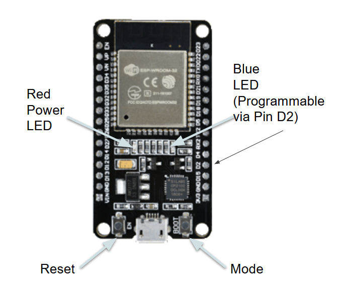
There are also 2 buttons: - EN: on the bottom left is a RESET button. You can use it to soft-power cycle the chip and restart the code you install - BOOT: on the bottom right is a programmable button. You can use it in your project to initiate a user event
Finally, you have a USB port and you can use this to connect your USB to your laptop to power it up and install your program.
Notice when you connect your USB that there are 2 LEDs: - RED: Power indicator. If this turns off you are either diconnected from power or have introduced a short. - BLUE: Programmable indicator. When you reset/power-cycle the board, this will blink 3 times. After that it may behave in various ways that are usage-dependent. You can program this using Pin2 on the ESP32.
PINs
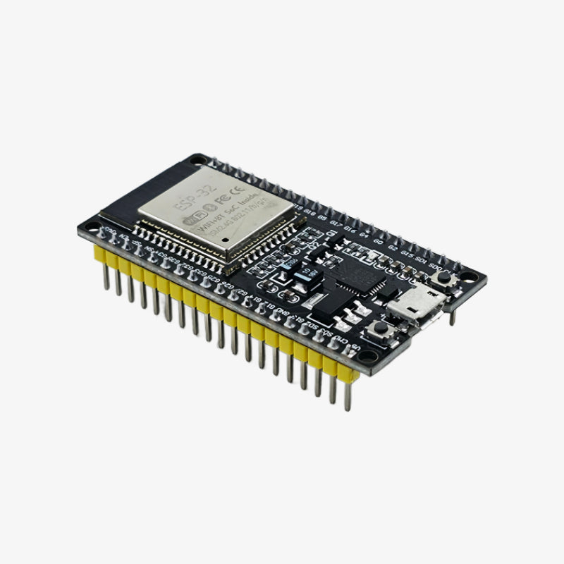
Look at the back of the ESP32 - you can see 30 pins (15 on each side) sticking out from the bottom of the board. We will learn how to use these as we go to control various actuators and take reads from various sensors.
 This is a pinout reference that may come in handy at some point in the future.
On the front you can see very small labels for each pin, like 3V3, GND, D2, and so on...
3V3 and GND are power pins. You can connect them to other electronics to supply 3.3V power. 3V3 would act as the +/anode point. GND would be the -/cathode.
D2 is internally connected to the Blue LED. You can turn D2 on/off to control that LED...
Let's test that!